
HESYS SETTLEMENT / ENGINEERING TRIAL
Tunnel & HDD
settlement analysis.
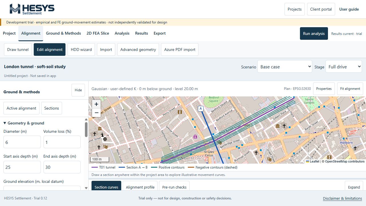
Model tunnel and HDD ground movement in your browser. Map settlement contours, inspect movement curves and export your results. Explore a separate 2D FE slice for a closer look.
Browser-based software · Authorised account access · Development trial, not independently validated for design
See the workflow in 38 seconds.
Change an input, run the assessment and review contours, curves, exports and a separate FE slice.
Read the short walkthrough
- Define tunnel geometry and ground-loss inputs.
- Change volume loss from 1% to 1.5%, then run the analysis to update the contours.
- Review settlement and horizontal movement curves; explore CAD, GIS, Google Earth and Excel exports.
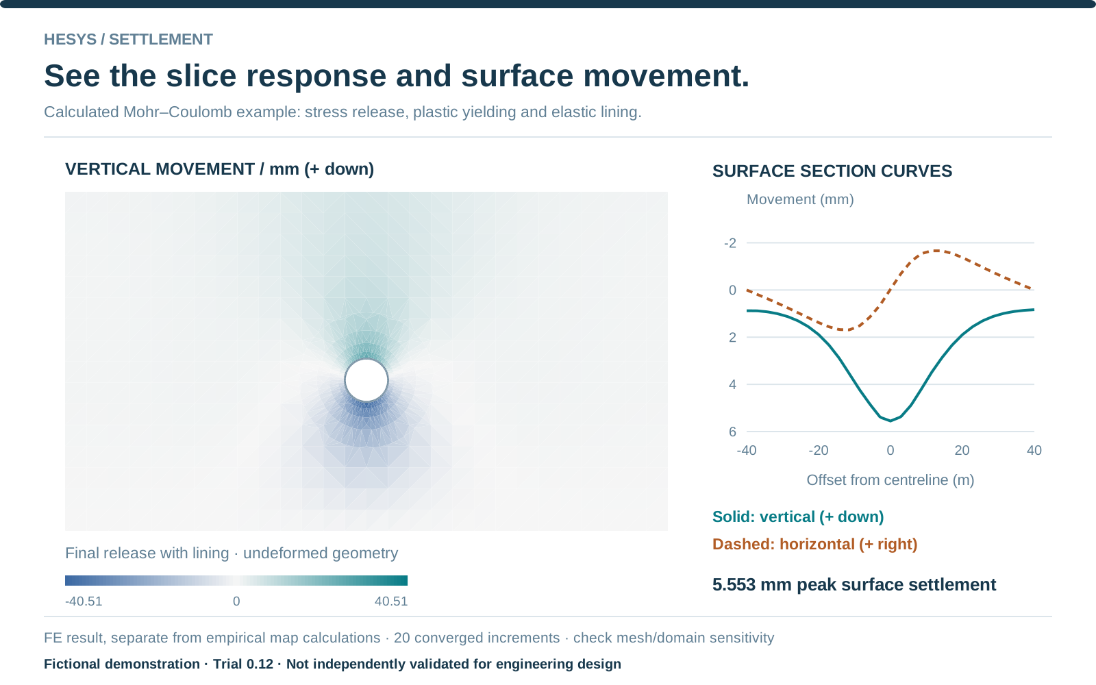
- Load and run the separate dry Mohr–Coulomb FE example. Inspect its parameters, mesh, movement field and surface curves.
Development trial; independent engineering validation is required. FE results are separate from empirical map contours. Download the map workspace image ↓
01 / DEFINE THE GEOMETRY
Tunnel and HDD
alignment inputs.
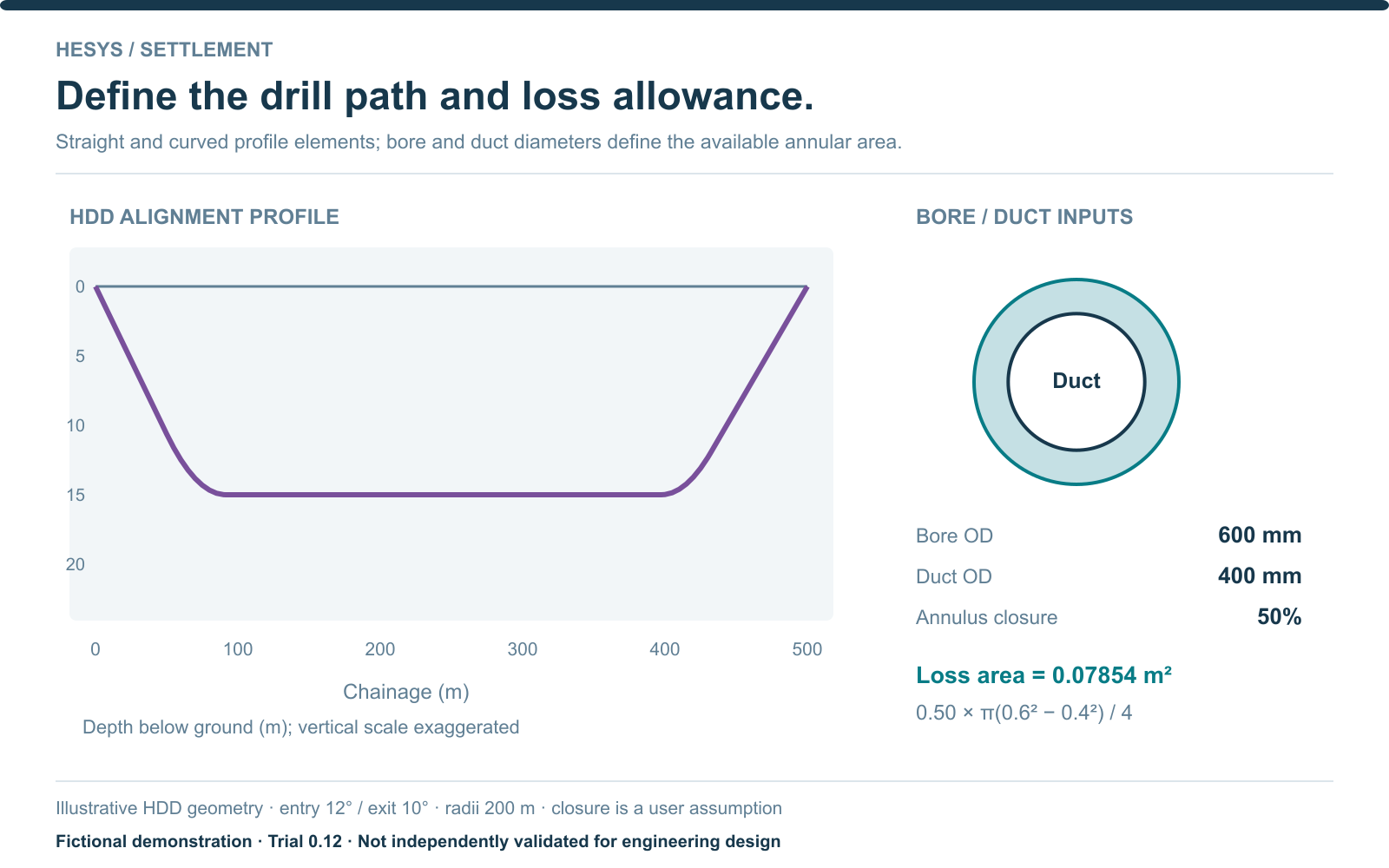
Draw a tunnel on the map or import an alignment. Build HDD profiles from straights and curves, then define bore diameter, duct diameter and assumed annulus closure.
Technical detail
Supported imports include CSV/Excel, DXF, GeoJSON, KML and supported LandXML geometry. Check coordinates, units and datum before applying.
02 / PUT MOVEMENT ON THE MAP
Settlement contours
in project context.
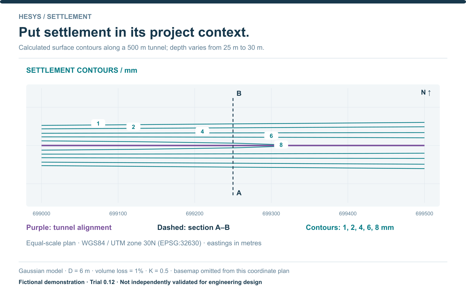
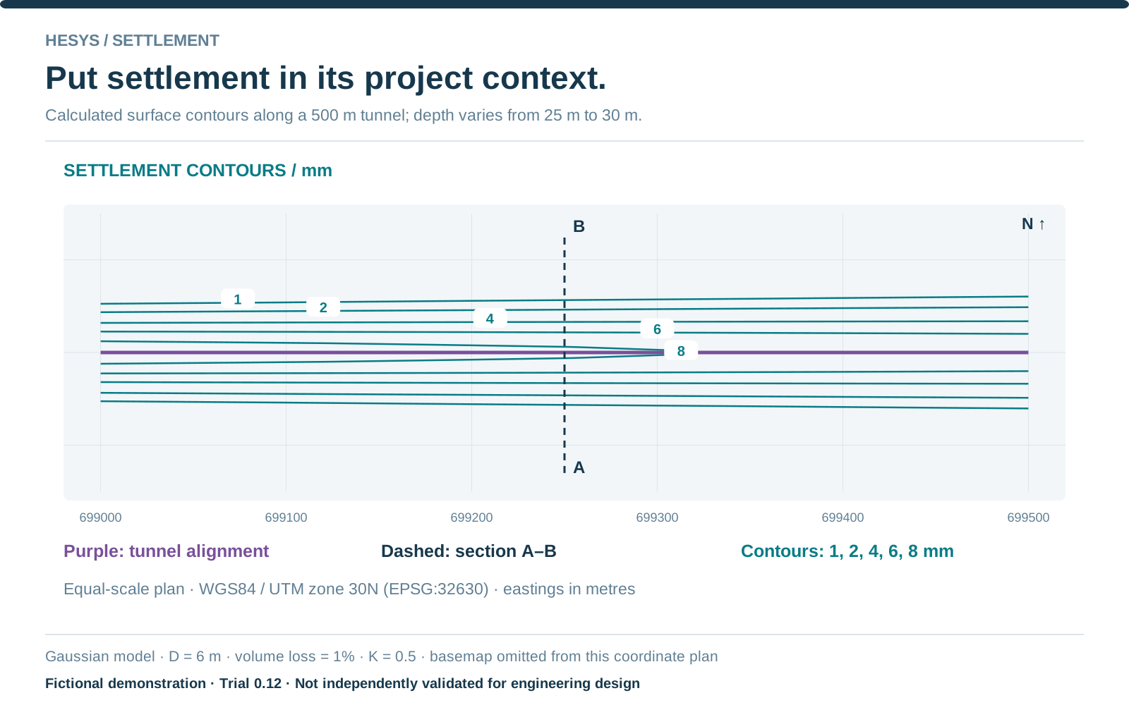
See settlement contours in map context. Set the contour spacing and choose an assessment method suited to your ground conditions.
Technical detail
Methods include user-defined Gaussian K, O’Reilly–New cohesive surface and Mair clay subsurface options. Current mapping uses WGS84 / UTM zone 30N.
03 / DRAW A SECTION. READ THE RESPONSE.
Settlement and
horizontal movement.
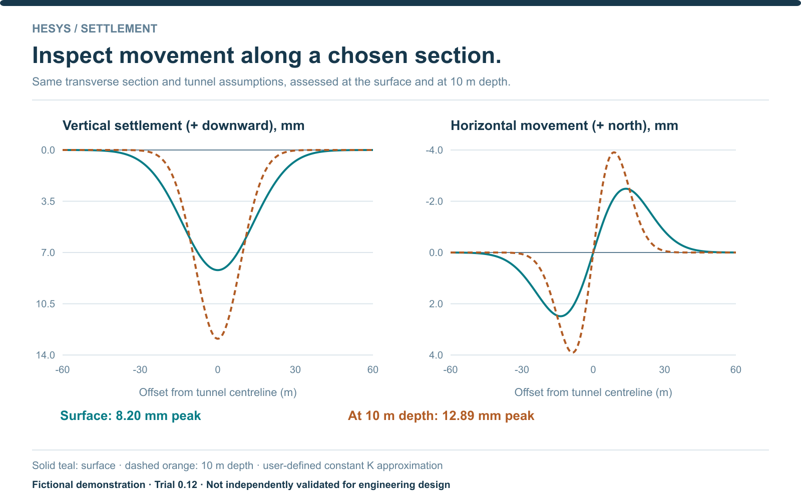
Draw a section across the assessment area to inspect settlement and horizontal movement. Set an assessment depth to explore subsurface response.
Technical detail
The example compares surface and 10 m depth results. Ground movement is estimated; utility interaction, strain and damage are not calculated.
04 / TAKE THE RESULT FURTHER
Export to CAD,
GIS and Google Earth.
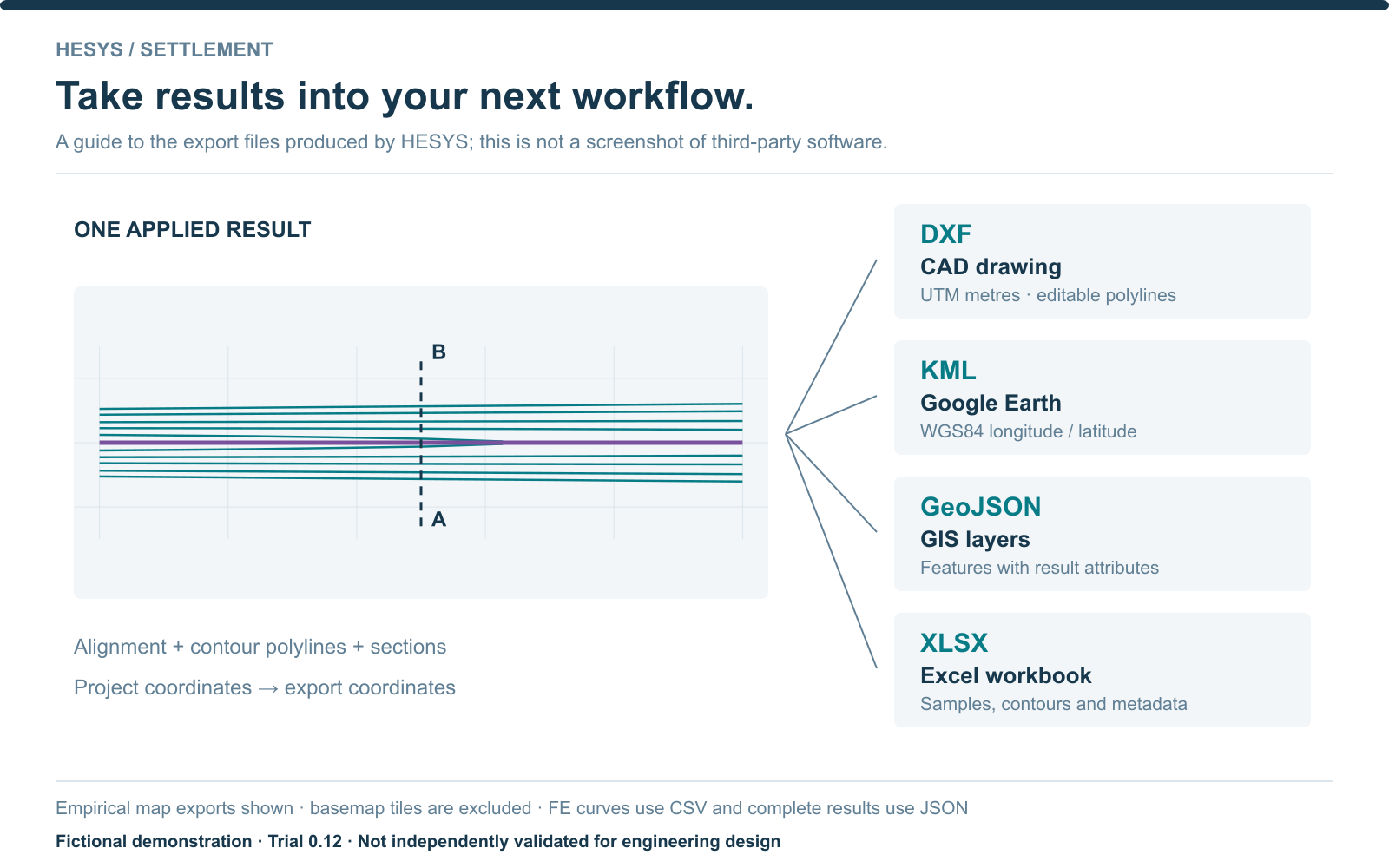
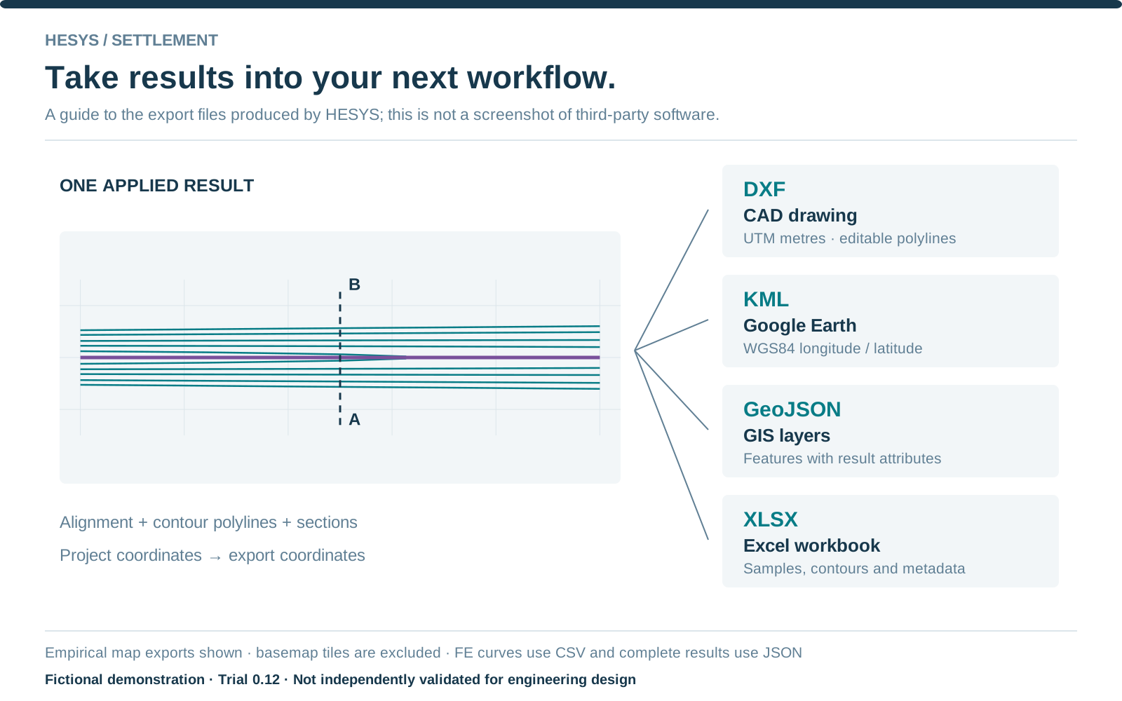
Take contours and alignments into CAD, GIS and Google Earth. Export results to Excel and copy report figures into Word.
Technical detail
DXF uses project metres; KML and GeoJSON use WGS84 longitude/latitude. Check the receiving coordinate system. Basemap tiles are excluded.
05 / EXAMINE A 2D TUNNEL SLICE
Ground profile.
Parameters. Mesh.
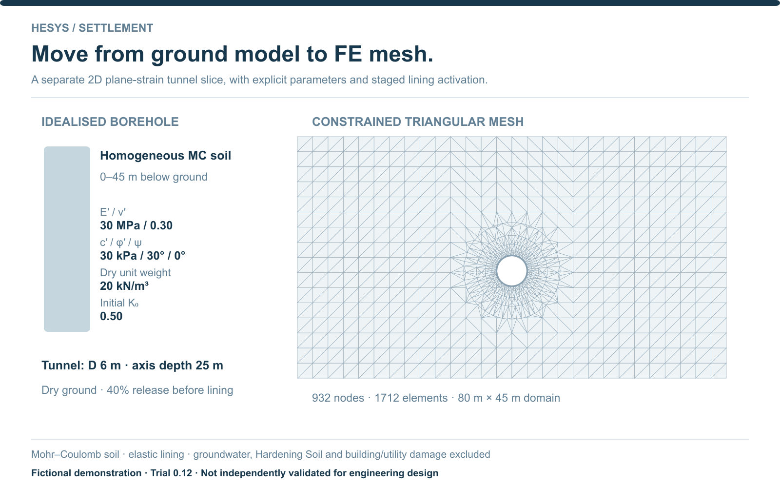
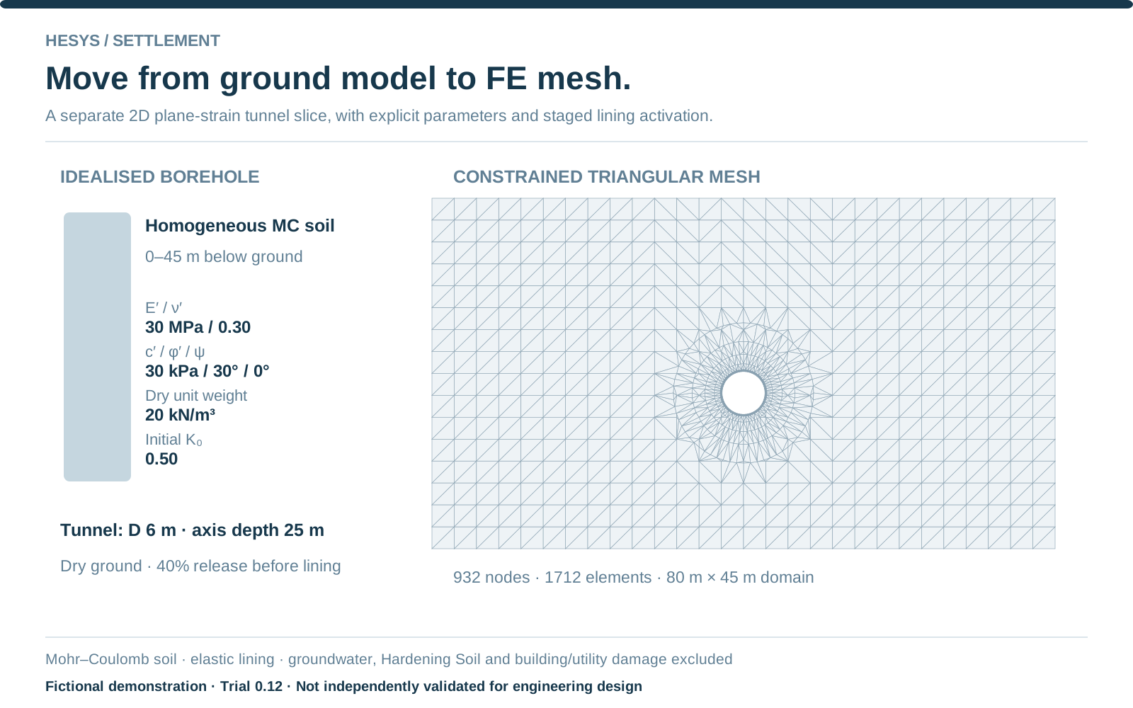
Build an idealised borehole or import layer depths from CSV. Assign soil parameters, define the tunnel and lining, then run a meshed 2D slice.
Technical detail
The current FE trial supports dry, drained, small-strain plane strain with linear-elastic or Mohr–Coulomb soil and an elastic lining.
Follow the stages.
Review the curves.
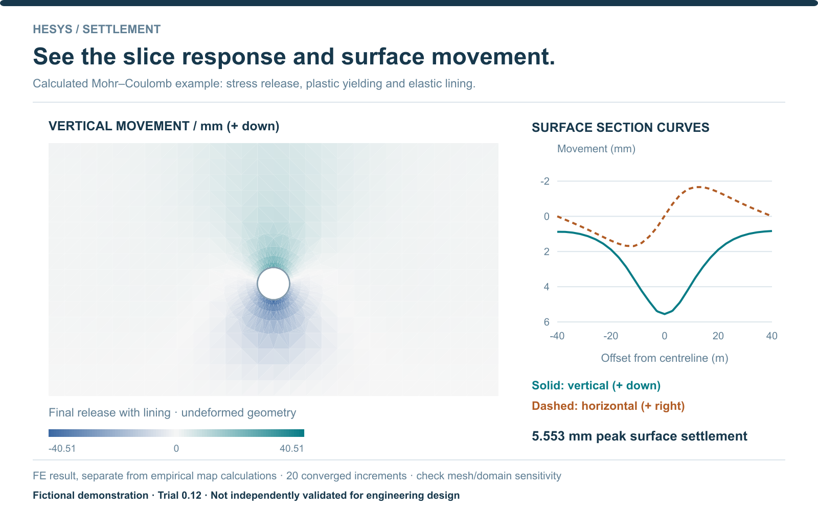
Review construction stages, ground-movement fields and selected-depth curves. Export figures and result data for your report.
This fictional example gives 5.553 mm peak surface settlement. FE outputs remain separate from the empirical map contours.
06 / KEEP THE VISUALS
Product image pack.
Seven PNG images, six editable SVG diagrams and a source note. All models are fictional. Keep the example labels, trial status and map attribution when reusing the images.
EXPLORE HESYS SETTLEMENT
Bring your workflow
to the trial.
Discuss your tunnel or HDD ground-movement assessment with Howl Engineering.